
Performance Analysis of Molybdenum Trioxide (MoO3) as an Inorganic Hole Transport Layer for Perovskite Solar Cells
تحليل أداء ثالث أكسيد الموليبدينوم (MoO3) كطبقة غير عضوية لنقل الفجوات في خلايا البيروفسكايت الشمسية
Altaib Eisa Haroon1, Taha Adam Abdalla 2,Amel Abdallah Ahmed Elfaki3
1, 3 Department of Physics, Faculty of Science, University of Sudan for Sciences and Technology, Sudan.
2 Department of Physics, Faculty of Education, University of Al Fashir, Sudan.
Correspondent author: altaib815@yahoo.com
DOI: https://doi.org/10.53796/hnsj610/34
Arabic Scientific Research Identifier: https://arsri.org/10000/610/34
Volume (6) Issue (10). Pages: 540 - 547
Received at: 2025-09-07 | Accepted at: 2025-09-15 | Published at: 2025-10-01
Abstract: This study aims to analyze the performance of molybdenum trioxide (MoO₃) as an inorganic hole transport layer (HTL) in perovskite solar cells (PSCs), taking advantage of its high thermal stability, optical transparency, and well-aligned energy levels. A comprehensive numerical simulation of a planar solar cell with the structure (FTO/TiO₂/Perovskite/MoO₃/Au) was conducted using COMSOL Multiphysics to evaluate the effects of active layer thickness, MoO₃ layer thickness, series resistance (Rₛ), and operating temperature on photovoltaic performance. The results revealed that parameters such as open-circuit voltage (V_oc), short-circuit current density (J_sc), fill factor (FF), and power conversion efficiency (PCE) are strongly influenced by these variables. Increasing the MoO₃ thickness was found to enhance hole extraction and improve V_oc, while high series resistance or elevated operating temperatures significantly reduced efficiency. These findings provide a theoretical framework and design guidelines for developing stable, high-performance PSCs employing MoO₃ as an inorganic HTL, thereby advancing their potential for practical and commercial applications.
Keywords: Perovskite solar cells, Molybdenum trioxide (MoO₃), Hole Transport Layer (HTL), COMSOL Multiphysics, Power Conversion Efficiency, Numerical Analysis.
المستخلص: تهدف هذه الدراسة إلى تحليل أداء ثالث أكسيد الموليبدينوم (MoO₃) بوصفه طبقة غير عضوية لنقل الفجوات (HTL) في خلايا البيروفسكايت الشمسية (PSCs)، وذلك من خلال الاستفادة من استقراره الحراري العالي، وشفافيته البصرية، ومواءمة مستوياته الطاقية مع طبقة البيروفسكايت. تم إجراء محاكاة عددية شاملة لخلية شمسية مستوية بهيكلية (FTO/TiO₂/Perovskite/MoO₃/Au) باستخدام برنامج COMSOL Multiphysics، بهدف تقييم تأثير السمك لكل من الطبقة النشطة وطبقة MoO₃، بالإضافة إلى تأثير المقاومة التسلسلية (Rₛ) ودرجة حرارة التشغيل على مؤشرات الأداء الكهروضوئي. أظهرت النتائج أن متغيرات مثل الجهد عند الدائرة المفتوحة (V_oc)، وكثافة التيار عند الدائرة القصيرة (J_sc)، ومعامل الامتلاء (FF)، وكفاءة تحويل الطاقة (PCE) تعتمد بشكل ملحوظ على هذه العوامل. كما تبين أن زيادة سمك MoO₃ يعزز استخلاص الفجوات ويُحسن V_oc، بينما يؤدي الارتفاع الكبير في المقاومة التسلسلية أو درجة الحرارة إلى انخفاض الكفاءة بشكل واضح. توفّر هذه النتائج إطارًا نظريًا إرشاديًا لتصميم وتحسين خلايا بيروفسكايت مستقرة ومرتفعة الكفاءة باستخدام مواد غير عضوية مثل MoO₃ لنقل الفجوات، الأمر الذي يعزز فرص تطويرها نحو التطبيقات العملية والتجارية.
الكلمات المفتاحية: خلايا البيروفسكايت الشمسية، ثالث أكسيد الموليبدينوم (MoO₃)، طبقة نقل الفجوات، COMSOL Multiphysics، كفاءة تحويل الطاقة، التحليل العددي.
1. Introduction
Perovskite solar cells (PSCs) have witnessed remarkable progress over the past decade, with their power conversion efficiency (PCE) soaring from 3.8% in 2009 to over 26% in recent lab-scale research (Kojima et al., 2009; NREL, 2025; Park, 2021). This escalating interest stems from their outstanding optoelectronic properties, such as a high absorption coefficient, excellent charge carrier mobility, and the potential for low-cost, solution-based fabrication (Snaith, 2022). A perovskite solar cell is composed of several layers, including the light-absorbing perovskite layer, an electron transport layer (ETL), and a hole transport layer (HTL) (Chen et al., 2021). The HTL is a vital component whose primary functions are to efficiently extract photogenerated holes from the perovskite layer and transport them to the back electrode while simultaneously blocking electrons to prevent recombination at the interface (Li et al., 2020).
Traditionally, organic materials like Spiro-OMeTAD have been widely used as HTLs. Despite their high performance, they suffer from issues related to chemical and thermal instability and high cost, which impede the commercialization of PSC technology (Kim et al., 2020). To overcome these challenges, inorganic materials have emerged as promising alternatives (Wang et al., 2021). Among them, Molybdenum trioxide (MoO₃) stands out as an ideal candidate due to its numerous advantages, including excellent chemical and thermal stability, high transparency in the visible spectrum, and a deep work function that aligns well with the valence band of perovskite materials, thereby facilitating efficient hole extraction (Wang et al., 2024; Wu et al., 2023).
Objectives and Contribution of the Study:
This study primarily aims to achieve the following objectives:
Firstly, systematic Analysis: To conduct a numerical analysis of the performance of a PSC that utilizes MoO₃ as an inorganic HTL. Secondly, parameter Optimization: To determine the precise impact of key device parameters (active layer thickness, MoO₃ layer thickness, series resistance, and operating temperature) on the cell’s photovoltaic metrics. Lastly, design Guideline Provision: To offer theoretical insights that contribute to the targeted optimization of MoO₃-based PSCs.
The primary contribution of this work is to provide a detailed, quantitative understanding of how these critical parameters affect cell performance. This offers a theoretical framework to guide experimental efforts toward fabricating more efficient and stable solar cells, thereby accelerating the transition from laboratory models to commercial applications (Yoo et al., 2021). Numerical simulation is a powerful tool for understanding and optimizing photovoltaic device performance, allowing a systematic study of various parameters while reducing the cost and time of experimental work (Singh et al., 2023). COMSOL Multiphysics, based on the finite element method, provides an integrated simulation environment for solving the coupled partial differential equations that govern solar cell operation, such as the Poisson and charge carrier continuity equations (Zai et al., 2020).
2. Methodology and Modeling
A planar n-i-p perovskite solar cell was simulated using the Semiconductor Module within COMSOL Multiphysics. The simulated device architecture consists of the following layers: Fluorine-doped Tin Oxide (FTO) as the front transparent contact, a layer of TiO2 as the ETL, a CH3NH3PbI3 perovskite layer as the active absorber, a layer as the HTL, and a Gold (Au) back contact. Figure 1(a) represents schematic structure of Perovskite Solar Cell made of/Au.
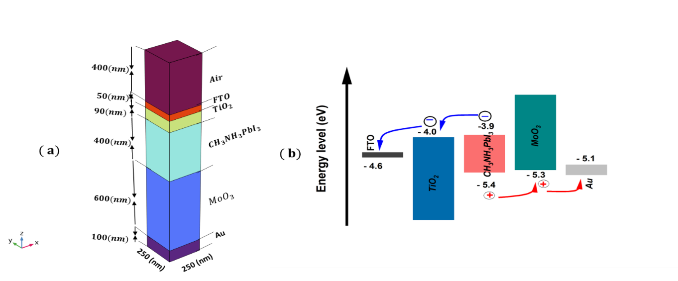
Figure 1.(a) Schematic structure of Perovskite Solar Cell made of/Au. (b)The corresponding energy level diagram.
Figure 1(b) Shows the energy level diagram, which is crucial for explaining the device’s operational mechanism. The diagram demonstrates a favorable “cascade” alignment for charge separation and transport:
- Electron Extraction: The conduction band minimum (CBM) of the TiO₂ ETL (-4.0 eV) is positioned slightly below that of the perovskite layer (-3.9 eV), creating a small energy step that drives the efficient extraction of photogenerated electrons from the perovskite into the ETL.
- Hole Extraction: The valence band maximum (VBM) of the HTL (-5.3 eV) is well-aligned with the VBM of the perovskite layer (-5.4 eV). This near-perfect alignment minimizes the energy barrier for hole extraction, facilitating their efficient transfer to the HTL.
- Charge Blocking: The deep VBM of and the high CBM of create large energy barriers that effectively block holes and electrons, respectively, preventing them from reaching the wrong electrode and thus minimizing charge recombination at the interfaces. This selective charge transport is fundamental for achieving high photovoltaic performance.
The carefully engineered band alignment is a key enabler for the high efficiency potential of PSCs using as the HTL.
The device was illuminated under a standard AM 1.5G solar spectrum with an incident power of 100 mW/cm². The model is based on solving the coupled Poisson’s equation and the drift-diffusion continuity equations for electrons and holes.
Where E, and are electric filed, wave number and respectively
The photogeneration rate G(x,y,z) was calculated by first solving Maxwell’s equations using the Wave Optics Module and then coupling the result to the semiconductor physics.
(2)
is the plank constant (Ali et al., 2023).
The generation rate of carriers in position (x, y, z) is calculated using the electric field inside each layer of the cell and is shown in the following equation:
Integration of over the wavelength range is performed and the total photo generation rate inside the solar cell is expressed as follows:
by solving Poisson’s Equation and continuity equations describe the dynamics of electrons and holes, at each mesh element in semiconductor module, the current voltage (J-V) Characteristics of the solar cell and the carrier concentration in the structure are obtained:
(4)
(5)
(6)
Where is the relative permittivity of semiconductor, is the electrostatic potential, is the total charge density and electric charge determined as follows equation:
) (7)
Where is the donor and acceptor doping concentration.
are the generation rates, and and are the recombination rates of electrons and holes, that can be calculated with the aid of Shockley Real Hall trapping model as follow:
where n and p are the electron and hole concentration, are the life times of electron and hole, intrinsic carrier concentration.
are the electron and hole current density, expressed by the electron and hole drift-diffusion charge transport equations as follows:
(9)
(10)
Where are the electron and hole mobility, are the electron and hole diffusion coefficient.
After obtaining the current density-voltage (J-V) characteristics of the solar cell, we can obtain the Power conservation efficiency of the solar cell as follows:
Where , and are the open-circuit voltage, the short-circuit current density and fill factor, respectively, maximum power , input power. The fill factor can be expressed as:
Where and current density and voltage at the maximum power point that are obtained from the J–V characteristic. The parameters were taken from the materials library or manually from the relevant literature. The physical parameters for each layer are given in Table 1, the band gap, the relative permittivity are effective conduction band and valance band densities, are electron and hole mobilities, χ is electron affinity, are acceptor and donor densities, and are the life times of electron and hole were defined based on values reported in recent scientific literature (Ali et al., 2023)
Table 1: Material proprieties used in this work.
|
Parameter |
|||
|
Thickness(nm) |
90 |
available |
400 |
|
3.2 |
1.55 |
3 |
|
|
9 |
6.5 |
12.5 |
|
|
4 |
3.92 |
2.5 |
|
|
– |
|||
|
– |
– |
||
|
20/10 |
50/50 |
25/100 |
|
|
5/2 |
8/8 |
5/5 |
3. Results and Discussion
3.1. Effect of Active Layer Thickness on Cell Performance
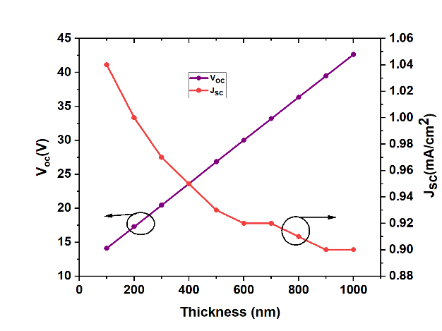
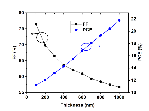
Figure 2. Effect of HTL thickness on cell performance, (a), vs thickness; (b) PCE, FF vs thickness
Figure 2(a) shows that as the thickness increases from 100 nm to 1000 nm, the increases monotonically, while the first increases, peaks around 500-600 nm, and then decreases. The initial rise in is due to enhanced light absorption. However, as the layer becomes thicker than the carrier diffusion length (~1 µm), photogenerated carriers are more likely to recombine before being collected, causing and FF to drop. The PCE, therefore, shows an optimal value at a thickness of around (500 nm), where the balance between absorption and collection is maximized. The increase in is attributed to enhanced light absorption and a higher density of photogenerated carriers in a thicker film. However, the drop in suggests that charge carrier collection becomes less efficient. As the layer thickens, the average distance carriers must travel to reach the transport layers increases, elevating the probability of bulk recombination before collection.
Figure 2(b) demonstrates the net effect of these opposing trends on the FF and PCE. Both parameters exhibit a significant decrease with increasing thickness. The decline is primarily driven by the reduction in and an increase in the device’s series resistance, which leads to a lower FF. This indicates that for this specific device structure , efficient charge collection is more critical than maximizing light absorption beyond a certain point. An optimal thickness exists that balances these factors, which, according to the graph, lies in the lower range (e.g., 100-300 nm) to maximize overall PCE.
3.2. Effect of MoO₃ Thickness on Cell Performance
The effect of varying the layer thickness on the solar cell’s performance was investigated. The results show that the thickness plays a dual role. On one hand, the layer must be thick enough to ensure complete, uniform coverage of the perovskite film, preventing any short-circuiting between the perovskite and the back contact. On the other hand, an excessively thick layer increases the device’s series resistance (), which impedes hole transport and reduces the fill factor (FF) and power conversion efficiency (PCE) .
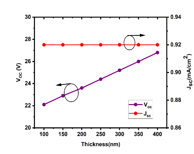
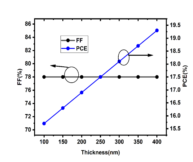
Figure 3. Effect of HTL thickness on cell performance, (a), vs thickness; (b), PCE, FF vs thickness.
The thickness of the HTL plays a significant role, Figure 3(a) Shows that the remains almost entirely constant as the thickness varies from 100 nm to 400 nm. This is expected, as has high transparency in the visible spectrum and does not contribute to photogeneration. In contrast, the shows a clear linear increase with thickness. This improvement can be attributed to the enhanced charge-blocking properties of a thicker HTL, which more effectively prevents electron recombination at the Au electrode, thereby reducing the diode saturation current and increasing .
Consequently, as shown in Figure 3(b), the PCE increases significantly with thickness, driven almost entirely by the rise in , while the FF remains stable at a high value of ~78%. This suggests that a thicker layer, within this range, is beneficial. However, it is well-established that an excessively thick HTL can increase series resistance, which would eventually lead to a drop in FF and PCE. Therefore, an optimal thickness must be identified that maximizes without introducing significant resistive losses.
3.3. Effect of Series resistance ()
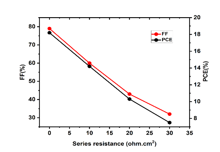
Figure 4. Effect of Series resistance on cell performance PCE, FF vs thickness.
Figure 4. Shows highlights the detrimental impact of parasitic series resistance (Rₛ) on device performance. As Rₛ increases from near zero to 30 ohm·cm², both the FF and PCE decrease dramatically. Series resistance arises from the bulk resistivity of the layers and the contact resistance at the interfaces. A higher Rₛ leads to increased ohmic losses (I²R), which dissipate power as heat rather than contributing to the output power. This is primarily reflected in a reduction of the fill factor, as the slope of the J-V curve at becomes less sharp. The direct consequence of a reduced FF is a lower PCE. This result underscores the critical importance of high-quality material deposition and interface engineering to minimize series resistance for fabricating high-efficiency solar cells.
3.4. Effect of Operating Temperature on Cell Performance
Studying solar cell performance under realistic operating conditions is essential, as the cell’s temperature naturally rises under solar illumination. The simulation results revealed that the performance of the perovskite solar cell is adversely affected by an increase in temperature.
 (b)
(b)
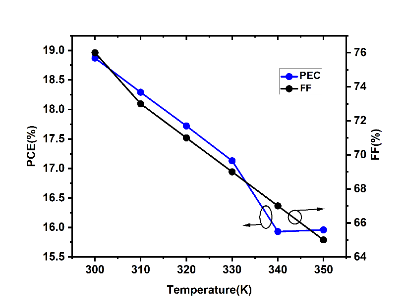
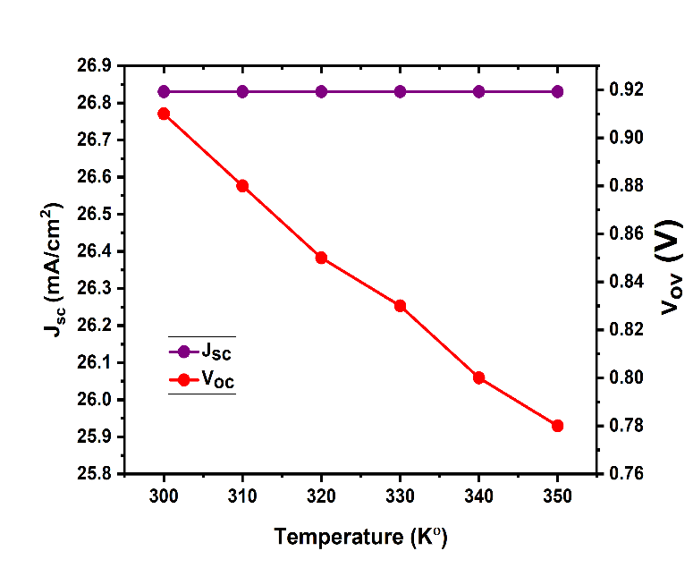
Figure 5. Effect of operation thickness on cell performance, (a), vs thickness; (b), PCE, FF vs thickness.
Figure 5. highlights the detrimental impact of parasitic series resistance. The thermal stability of PSCs is a key concern for real-world applications. The figure demonstrates that as the operating temperature increases from 300 K to 350 K, the device performance degrades. While the remains relatively stable, the exhibits a significant, near-linear decrease. This behavior is characteristic of most semiconductor-based solar cells and is primarily caused by an increase in the intrinsic carrier concentration () and the diode saturation current with temperature. The temperature dependence of is a dominant factor in the thermal degradation of performance.
Consequently, both the FF and PCE decline as the temperature rises. The degradation of and FF combine to produce a negative temperature coefficient for the PCE, indicating that the cell is less efficient at higher operating temperatures. This highlights the need for effective thermal management strategies in PSC modules and the ongoing research into developing more thermally stable device components.
4. Conclusion
In this study, the performance of a planar perovskite solar cell incorporating an inorganic MoO₃ hole transport layer was systematically investigated through numerical simulation. The study successfully achieved its objectives, as the analysis revealed that the device’s photovoltaic parameters are highly sensitive to the thicknesses of the active and hole transport layers, as well as to parasitic resistances and operating temperature.
An optimal perovskite layer thickness was identified as a trade-off between maximizing light absorption and ensuring efficient charge carrier collection, with thinner layers proving more effective in mitigating bulk recombination. Increasing the thickness of the MoO₃ HTL was found to be beneficial for enhancing by suppressing interfacial recombination, thereby boosting the overall PCE. Furthermore, the strong adverse effects of series resistance and elevated operating temperatures were quantified, underscoring the critical need for high-quality interfaces and effective thermal management.
The main contribution of these findings is the provision of a theoretical framework and valuable guidelines for the design and fabrication of high-performance, stable perovskite solar cells based on robust and cost-effective inorganic charge transport materials. These insights can guide researchers in the field to reduce the necessary number of experiments and optimize device performance more rapidly, supporting the advancement toward the commercialization of this promising technology.
5. References
Ali, A., Hameed, U., & Khan, A. D. (2023). Numerical modeling and optimization of perovskite solar cells with inorganic charge transport layers. Journal of Computational Electronics, 22(4), 1165–1174.
Chen, B., Rudd, P. N., Yang, S., Yuan, Y., & Huang, J. (2021). Imperfections and their passivation in metal halide perovskites. Chemical Society Reviews, 50(23), 13349-13399.
Correa-Baena, J. P., Yoo, J. J., & Grätzel, M. (2022). The scale-up of perovskite solar cells and modules. Nature Energy, 7(10), 885-896.
He, R., Wang, Y., & Chen, Q. (2022). Recent progress in inorganic hole transport materials for stable and efficient perovskite solar cells. Advanced Materials, 34(26), 2109503.
Jeong, M. J., Yeom, E. J., Kim, G., Choi, I. W., Choi, H., Lee, S., … & Seok, S. I. (2021). Stable and efficient perovskite solar cells via inorganic charge transport layer engineering. Science, 372(6543), 632-637.
Jiang, Q., Zhao, Y., Zhang, X., Yang, X., Chen, Y., Chu, Z., … & You, J. (2022). Scalable fabrication of >25% efficiency perovskite solar modules. Nature, 611(7935), 278-283.
Kim, H., Lee, J. W., Paik, M. J., Kim, G., Lee, H., Yun, A. J., … & Seok, S. I. (2020). Self-assembled monolayer enables hole transport layer-free, high-performance perovskite solar cells. Nature Communications, 11(1), 2244.
Kojima, A., Teshima, K., Shirai, Y., & Miyasaka, T. (2009). Organometal halide perovskites as visible-light sensitizers for photovoltaic cells. Journal of the American Chemical Society, 131(17), 6050–6051.
Li, Z., Li, B., Wu, X., Li, Y., Yang, S., Zhang, W., … & Chen, H. (2020). A universal hole-extraction layer for inverted perovskite solar cells. Science, 368(6487), eaaz7698.
Liu, C., Sun, W., Liu, Z., Yang, Y., Li, F., Yu, Y., … & Liu, S. F. (2023). Interface passivation using zwitterions for efficient and stable perovskite solar cells. Joule, 7(5), 1032-1046.
National Renewable Energy Laboratory. (2025). Best research-cell efficiency chart. Retrieved from https://www.nrel.gov/pv/cell-efficiency.html
Singh, S., & Kumar, M. (2023). A review on numerical simulation of perovskite solar cells using SCAPS-1D. Solar Energy, 255, 247-268.
Snaith, H. J. (2022). Perovskite solar cells: From the laboratory to the marketplace. Advanced Materials, 34(44), 2108129.
Wang, H., Chen, C., & Zhu, F. (2021). Dopant-free inorganic hole transport layers for efficient and stable perovskite solar cells. Angewandte Chemie International Edition, 60(29), 15774-15794.
Wang, P., Li, R., & Chen, W. (2024). Molybdenum oxides as interfacial layers in perovskite solar cells: Progress and prospects. Chemical Engineering Journal, 479, 147775.
Wu, W. Q., Liu, Z. K., Wang, Z. K., & Liao, L. S. (2023). Thermally stable perovskite solar cells with MoOₓ/Spiro-OMeTAD composite hole transport layer. Solar RRL, 7(3), 2200891.
Xiang, W., Wang, Z., Kubicki, D. J., Tress, W., & Zakeeruddin, S. M. (2022). Suppressing ion migration in perovskite solar cells through grain boundary passivation. Nature Communications, 13(1), 3294.
Yoo, J. J., Seo, G., Chua, M. R., Park, T. G., Lu, Y., Rothenberger, F., … & Zakeeruddin, S. M. (2021). Efficient and stable perovskite solar cells with a tailored 2D/3D heterojunction. Nature, 590(7847), 587-593.
Zai, H., Zhu, H., & Huang, T. (2020). Defect passivation in perovskite solar cells: A review. Advanced Science, 7(15), 2001157.
Zhang, F., Lu, H., & Zhu, L. (2021). Ion-migration suppression in perovskite solar cells for enhanced operational stability. Nature Communications, 12(1), 5418.
Zhang, T., Wang, F., & Yang, S. (2024). Interface engineering of inorganic transport layers for perovskite solar cells with efficiency exceeding 25%. Joule, 8(1), 221-235.
Zhao, D., Chen, C., Wang, C., & Jiao, Y. (2022). High-performance inverted perovskite solar cells with efficiency over 23% by using a fullerene derivative as an electron transport layer. Advanced Materials, 34(15), 2108508.
Zhou, Y., Wang, F., & Hayat, T. (2020). Interface engineering for high-performance metal halide perovskite solar cells. Advanced Energy Materials, 10(13), 1903930.